The most distinct advantage of using a MIDI interface is that this works for all kinds of computers or operating systems (including Linux, Windows, and MacOS).
B. Microcontrollers: Arduino or Teensy
I have built and tested two such devices, one using the very popular "ArduinoUno" micro-controller board, and the other using
the "Teensy 2.0" board. Both cost about 20 Euros (or Dollars). While the Arduino is probably more popular, building a MIDI
interface with the Teensy board is actually easier. But here I will describe both cases. If you want to keep it simple,
skip the Arduino section C and jump directly to section D.
C. Arduino as MIDI controller
What you need:
Two ArduinoUno boards, the Arduino IDE, and a separate command-line program called "avrdude".
While this is part of the Arduino IDE already, I have installed it sepearately on my Macintosh computer. The same would apply to Linux
but I do not know how to run "avrdude" on Windows. If you know, tell me and I put this information in this place.
The ArduinoUno actually features two micro-controllers: the one you usually program is the Atmega 328p, but there is, in addition,
a 16U2 microcontroller on the board which does the USB-to-serial conversion. There might be Arduino clones on the market which
use a standard USB-to-serial chip but these cannot be used for this project!
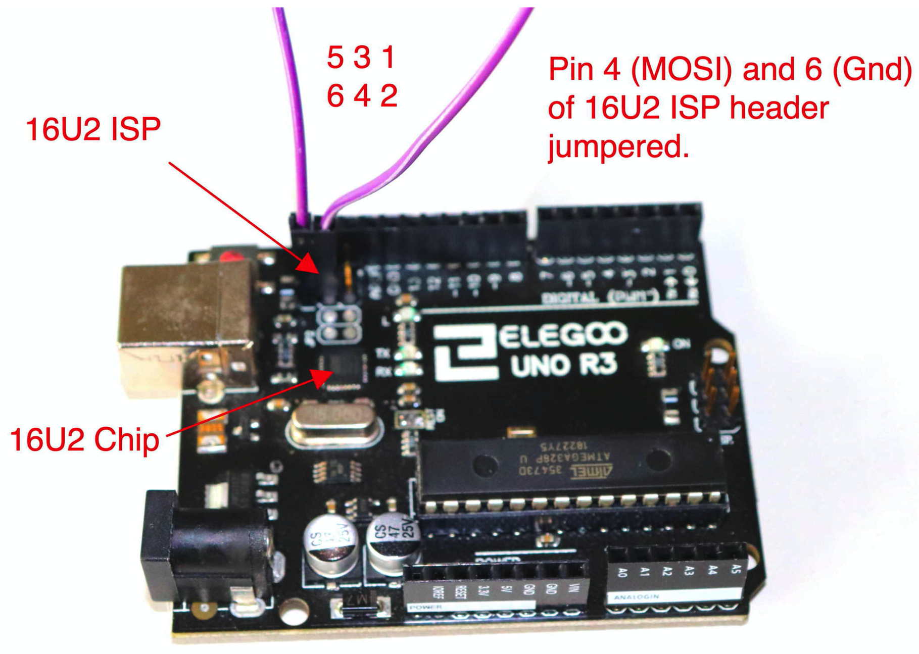
This picture shows an ArduinoUno (Clone), and the 16U2 chip and its in-system-programming (ISP) connector is shown as well.
This ISP connector has 6 pins. The 16U2 must be re-programmed such that the Arduino shows up as a MIDI device (and not as
a serial interface) to the computer. However there is a problem: if you want to "burn" a sketch onto the Arduino, the 16U2
must behave as a serial interface, if you want to used it, it must show up as a MIDI device. The solution is the so-called
"dualMOCO" firmware for the 16U2 which can be found
here as a HEX-file with file name dualmoco.hex.
The difficult thing is now to "burn" this Hex-file into the 16U2 chip. If you are used to programming micro-controllers,
you most likely have such a programmer and have no difficulties. Here I describe how to do this with a second
Arduino used as a programmer. I will refer to the Arduino where the 16U2 chip shall be re-programmes as the "MIDIArduino"
and the Arduino which does the programming as the "ProgrammingArduino". The ProgrammingArduino is only used once.
Programming the 16U2 chip:
Connect the ProgrammingArduino to your computer as usual and open the Arduino IDE. From the
Examples menu, choose the "Arduino ISP" example and load this sketch on to the ProgrammingArduino.
Connect pins 1,3 and 2,4,6 of the main ISP of the ProgrammingArduino with the respective pins of
the 16U2 ISP of the MIDIArduino, and digital pin D10 of the ProgrammingArduino with pin 5 (Reset) of
the 16U2 ISP of the MIDIArduino. This connection also powers up the MIDIArduino board (note both boards
run at 5 Volts). To use the avrdude program, you have to write down the name of the serial interface
associated with the ProgrammingArduino. On my Macintosh, this was /dev/usbmodem146401 but this may vary
and is certainly different on other operating systems.
First we make a backup of the firmware inside the 16U2 chip, using the command
avrdude -c stk500v1 -b 19200 -P /dev/tty.usbmodem146401 -p m16u2 -Uflash:r:backup.hex:i
This places the firmware image into the file "backup.hex". Of course, replace /dev/tty.usbmodem146401 by
the device name of the serial interface of the ProgrammingArduino. Then the new firmware is loaded
into the 16U2 chip of the MIDIArduino using the command (assuming the new firmware file "dualmoco.hex"
is in the current directory)
avrdude -c stk500v1 -b 19200 -P /dev/tty.usbmodem146401 -p m16u2 -Uflash:w:dualmoco.hex:i
Uploading the MIDI-CW sketch:
Disconnecting everything from the 16U2 ISP header of the MIDIArduino and connecting it to a computer, it
will show up as a MIDI device with name "MocoLUFA". However it does not do any work yet because we
have to upload a sketch which implements our CW-to-MIDI function. To upload a sketch, disconnect the
MIDIArduino and connect pin 4 and 6 of the 16U2 ISP header, as shown in the above figure.
If the jumper is present when connecting the MIDIArduino to a computer, it will show up as a serial
interface and can be programmed as usual from within the Arduino IDE.
The sketch itself is given in sec. F at the bottom of this page. It works "as is" with the Teensy, to
use it with the Arduino you have to replace the line
"#define TEENSY_USBMIDI" with
"#define ARDUINO_MOCOLUFA". As it stands, the left CW paddle should shorten digital input D2 to ground,
the right paddle D3 and the PTT input D4. Midi messages are generated on MIDI channel 5, with the notes
32 (left paddle), 33 (right paddle) and 34 (PTT), and a "NoteON" message is generated if the contact is
closed, and a "NoteOff" message if it opens.
D. Teensy 2.0 as MIDI controller
What you need:
A Teensy2.0 board, the Arduino IDE with Teensy extensions. These extensions are available
on the manufactuer's web site. In the case of MacOS, there is a single download for the Arduino IDE with
Teensy extensions.
You simply open the IDE and copy-and-paste the sketch given blow into the IDE main window. This sketch uses the input pins 0,1,2 of the
Teensy2.0 for left/right paddle and PTT. In the "Tools" menu, choose the correct board type (Teensy 2.0) and "MIDI" for the USB type.
Without the correct USB type, the program won't even compile. To upload the sketch, you have to press the small button on the Teensy board.
That's it.
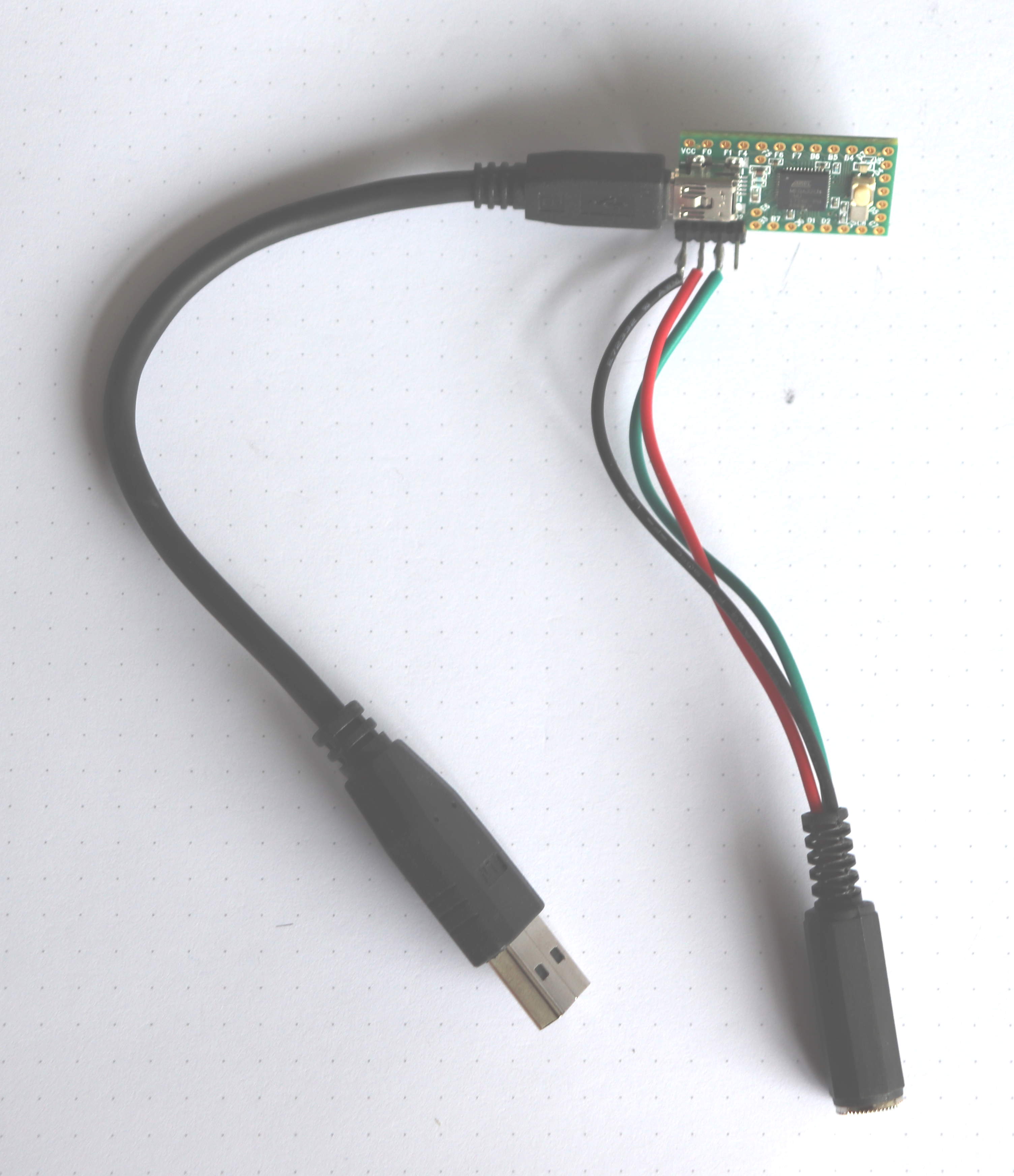
The figure shows a Teensy2.0 board with a small USB cable plugged in (the other end goes into the computer)
and a 3.5mm stereo jack for connecting a paddle (sleeve: ground, ring and tip: left/right paddle).
E. Using the MIDI controller with piHPSDR
To use this controller with the piHPDSR software, simply "import" the following MIDI description
file from the piHPSDR start menu. If you are already using another MIDI controller, just insert
the following lines at the top of you MIDI description file.
DEVICE=Teensy MIDI
KEY=32 CHAN=5 ACTION=CWL ONOFF
KEY=33 CHAN=5 ACTION=CWR ONOFF
KEY=34 CHAN=5 ACTION=PTT ONOFF
If you are using the Arduino as MIDI controller you have to replace "Teensy MIDI" with
"MocoLUFA".
F. The sketch.
The sketch can be opened as a text file with this link. Either
copy this file on your hard-disk or open a new project in the Arduino IDE and copy-and-paste the
program there.
DL1YCF, October 2020
Two ArduinoUno boards, the Arduino IDE, and a separate command-line program called "avrdude".
While this is part of the Arduino IDE already, I have installed it sepearately on my Macintosh computer. The same would apply to Linux
but I do not know how to run "avrdude" on Windows. If you know, tell me and I put this information in this place.
The ArduinoUno actually features two micro-controllers: the one you usually program is the Atmega 328p, but there is, in addition,
a 16U2 microcontroller on the board which does the USB-to-serial conversion. There might be Arduino clones on the market which
use a standard USB-to-serial chip but these cannot be used for this project!
This picture shows an ArduinoUno (Clone), and the 16U2 chip and its in-system-programming (ISP) connector is shown as well.
This ISP connector has 6 pins. The 16U2 must be re-programmed such that the Arduino shows up as a MIDI device (and not as
a serial interface) to the computer. However there is a problem: if you want to "burn" a sketch onto the Arduino, the 16U2
must behave as a serial interface, if you want to used it, it must show up as a MIDI device. The solution is the so-called
"dualMOCO" firmware for the 16U2 which can be found
here as a HEX-file with file name dualmoco.hex.
The difficult thing is now to "burn" this Hex-file into the 16U2 chip. If you are used to programming micro-controllers,
you most likely have such a programmer and have no difficulties. Here I describe how to do this with a second
Arduino used as a programmer. I will refer to the Arduino where the 16U2 chip shall be re-programmes as the "MIDIArduino"
and the Arduino which does the programming as the "ProgrammingArduino". The ProgrammingArduino is only used once.
Programming the 16U2 chip:
Connect the ProgrammingArduino to your computer as usual and open the Arduino IDE. From the
Examples menu, choose the "Arduino ISP" example and load this sketch on to the ProgrammingArduino.
Connect pins 1,3 and 2,4,6 of the main ISP of the ProgrammingArduino with the respective pins of
the 16U2 ISP of the MIDIArduino, and digital pin D10 of the ProgrammingArduino with pin 5 (Reset) of
the 16U2 ISP of the MIDIArduino. This connection also powers up the MIDIArduino board (note both boards
run at 5 Volts). To use the avrdude program, you have to write down the name of the serial interface
associated with the ProgrammingArduino. On my Macintosh, this was /dev/usbmodem146401 but this may vary
and is certainly different on other operating systems.
First we make a backup of the firmware inside the 16U2 chip, using the command
avrdude -c stk500v1 -b 19200 -P /dev/tty.usbmodem146401 -p m16u2 -Uflash:r:backup.hex:i
This places the firmware image into the file "backup.hex". Of course, replace /dev/tty.usbmodem146401 by
the device name of the serial interface of the ProgrammingArduino. Then the new firmware is loaded
into the 16U2 chip of the MIDIArduino using the command (assuming the new firmware file "dualmoco.hex"
is in the current directory)
avrdude -c stk500v1 -b 19200 -P /dev/tty.usbmodem146401 -p m16u2 -Uflash:w:dualmoco.hex:i
Uploading the MIDI-CW sketch:
Disconnecting everything from the 16U2 ISP header of the MIDIArduino and connecting it to a computer, it
will show up as a MIDI device with name "MocoLUFA". However it does not do any work yet because we
have to upload a sketch which implements our CW-to-MIDI function. To upload a sketch, disconnect the
MIDIArduino and connect pin 4 and 6 of the 16U2 ISP header, as shown in the above figure.
If the jumper is present when connecting the MIDIArduino to a computer, it will show up as a serial
interface and can be programmed as usual from within the Arduino IDE.
The sketch itself is given in sec. F at the bottom of this page. It works "as is" with the Teensy, to
use it with the Arduino you have to replace the line
"#define TEENSY_USBMIDI" with
"#define ARDUINO_MOCOLUFA". As it stands, the left CW paddle should shorten digital input D2 to ground,
the right paddle D3 and the PTT input D4. Midi messages are generated on MIDI channel 5, with the notes
32 (left paddle), 33 (right paddle) and 34 (PTT), and a "NoteON" message is generated if the contact is
closed, and a "NoteOff" message if it opens.
D. Teensy 2.0 as MIDI controller
What you need:
A Teensy2.0 board, the Arduino IDE with Teensy extensions. These extensions are available
on the manufactuer's web site. In the case of MacOS, there is a single download for the Arduino IDE with
Teensy extensions.
You simply open the IDE and copy-and-paste the sketch given blow into the IDE main window. This sketch uses the input pins 0,1,2 of the
Teensy2.0 for left/right paddle and PTT. In the "Tools" menu, choose the correct board type (Teensy 2.0) and "MIDI" for the USB type.
Without the correct USB type, the program won't even compile. To upload the sketch, you have to press the small button on the Teensy board.
That's it.
The figure shows a Teensy2.0 board with a small USB cable plugged in (the other end goes into the computer)
and a 3.5mm stereo jack for connecting a paddle (sleeve: ground, ring and tip: left/right paddle).
E. Using the MIDI controller with piHPSDR
To use this controller with the piHPDSR software, simply "import" the following MIDI description
file from the piHPSDR start menu. If you are already using another MIDI controller, just insert
the following lines at the top of you MIDI description file.
DEVICE=Teensy MIDI
KEY=32 CHAN=5 ACTION=CWL ONOFF
KEY=33 CHAN=5 ACTION=CWR ONOFF
KEY=34 CHAN=5 ACTION=PTT ONOFF
If you are using the Arduino as MIDI controller you have to replace "Teensy MIDI" with
"MocoLUFA".
F. The sketch.
The sketch can be opened as a text file with this link. Either
copy this file on your hard-disk or open a new project in the Arduino IDE and copy-and-paste the
program there.
DL1YCF, October 2020
This picture shows an ArduinoUno (Clone), and the 16U2 chip and its in-system-programming (ISP) connector is shown as well. This ISP connector has 6 pins. The 16U2 must be re-programmed such that the Arduino shows up as a MIDI device (and not as a serial interface) to the computer. However there is a problem: if you want to "burn" a sketch onto the Arduino, the 16U2 must behave as a serial interface, if you want to used it, it must show up as a MIDI device. The solution is the so-called "dualMOCO" firmware for the 16U2 which can be found here as a HEX-file with file name dualmoco.hex.
The difficult thing is now to "burn" this Hex-file into the 16U2 chip. If you are used to programming micro-controllers, you most likely have such a programmer and have no difficulties. Here I describe how to do this with a second Arduino used as a programmer. I will refer to the Arduino where the 16U2 chip shall be re-programmes as the "MIDIArduino" and the Arduino which does the programming as the "ProgrammingArduino". The ProgrammingArduino is only used once.
Programming the 16U2 chip:
Connect the ProgrammingArduino to your computer as usual and open the Arduino IDE. From the
Examples menu, choose the "Arduino ISP" example and load this sketch on to the ProgrammingArduino.
Connect pins 1,3 and 2,4,6 of the main ISP of the ProgrammingArduino with the respective pins of
the 16U2 ISP of the MIDIArduino, and digital pin D10 of the ProgrammingArduino with pin 5 (Reset) of
the 16U2 ISP of the MIDIArduino. This connection also powers up the MIDIArduino board (note both boards
run at 5 Volts). To use the avrdude program, you have to write down the name of the serial interface
associated with the ProgrammingArduino. On my Macintosh, this was /dev/usbmodem146401 but this may vary
and is certainly different on other operating systems.
First we make a backup of the firmware inside the 16U2 chip, using the command
avrdude -c stk500v1 -b 19200 -P /dev/tty.usbmodem146401 -p m16u2 -Uflash:r:backup.hex:i
This places the firmware image into the file "backup.hex". Of course, replace /dev/tty.usbmodem146401 by
the device name of the serial interface of the ProgrammingArduino. Then the new firmware is loaded
into the 16U2 chip of the MIDIArduino using the command (assuming the new firmware file "dualmoco.hex"
is in the current directory)
avrdude -c stk500v1 -b 19200 -P /dev/tty.usbmodem146401 -p m16u2 -Uflash:w:dualmoco.hex:i
Uploading the MIDI-CW sketch:
Disconnecting everything from the 16U2 ISP header of the MIDIArduino and connecting it to a computer, it
will show up as a MIDI device with name "MocoLUFA". However it does not do any work yet because we
have to upload a sketch which implements our CW-to-MIDI function. To upload a sketch, disconnect the
MIDIArduino and connect pin 4 and 6 of the 16U2 ISP header, as shown in the above figure.
If the jumper is present when connecting the MIDIArduino to a computer, it will show up as a serial
interface and can be programmed as usual from within the Arduino IDE.
The sketch itself is given in sec. F at the bottom of this page. It works "as is" with the Teensy, to
use it with the Arduino you have to replace the line
"#define TEENSY_USBMIDI" with
"#define ARDUINO_MOCOLUFA". As it stands, the left CW paddle should shorten digital input D2 to ground,
the right paddle D3 and the PTT input D4. Midi messages are generated on MIDI channel 5, with the notes
32 (left paddle), 33 (right paddle) and 34 (PTT), and a "NoteON" message is generated if the contact is
closed, and a "NoteOff" message if it opens.
D. Teensy 2.0 as MIDI controller
What you need:
A Teensy2.0 board, the Arduino IDE with Teensy extensions. These extensions are available
on the manufactuer's web site. In the case of MacOS, there is a single download for the Arduino IDE with
Teensy extensions.
You simply open the IDE and copy-and-paste the sketch given blow into the IDE main window. This sketch uses the input pins 0,1,2 of the
Teensy2.0 for left/right paddle and PTT. In the "Tools" menu, choose the correct board type (Teensy 2.0) and "MIDI" for the USB type.
Without the correct USB type, the program won't even compile. To upload the sketch, you have to press the small button on the Teensy board.
That's it.
The figure shows a Teensy2.0 board with a small USB cable plugged in (the other end goes into the computer)
and a 3.5mm stereo jack for connecting a paddle (sleeve: ground, ring and tip: left/right paddle).
E. Using the MIDI controller with piHPSDR
To use this controller with the piHPDSR software, simply "import" the following MIDI description
file from the piHPSDR start menu. If you are already using another MIDI controller, just insert
the following lines at the top of you MIDI description file.
DEVICE=Teensy MIDI
KEY=32 CHAN=5 ACTION=CWL ONOFF
KEY=33 CHAN=5 ACTION=CWR ONOFF
KEY=34 CHAN=5 ACTION=PTT ONOFF
If you are using the Arduino as MIDI controller you have to replace "Teensy MIDI" with
"MocoLUFA".
F. The sketch.
The sketch can be opened as a text file with this link. Either
copy this file on your hard-disk or open a new project in the Arduino IDE and copy-and-paste the
program there.
DL1YCF, October 2020
First we make a backup of the firmware inside the 16U2 chip, using the command
avrdude -c stk500v1 -b 19200 -P /dev/tty.usbmodem146401 -p m16u2 -Uflash:r:backup.hex:i
This places the firmware image into the file "backup.hex". Of course, replace /dev/tty.usbmodem146401 by the device name of the serial interface of the ProgrammingArduino. Then the new firmware is loaded into the 16U2 chip of the MIDIArduino using the command (assuming the new firmware file "dualmoco.hex" is in the current directory)
avrdude -c stk500v1 -b 19200 -P /dev/tty.usbmodem146401 -p m16u2 -Uflash:w:dualmoco.hex:i