Reviving/Modifiying a Yaesu FL-2100
RF tube power amplifier

> Rewiring the AC mains connection

The first thing I did was to re-wire the primary side of the main transformer for 237 V. Originally is was wired for 220 Volts, but meanwhile our Voltage is 230 Volt, so I wanted to be on the safe side. There is a little bit of under-voltage now, but this cannot do much harm, on the contrary, it may extend the life of various components including the tubes. The measured standby anode voltage is 2150 Volts (this agrees with the reading of the built-in meter), so there seems to be some headroom at first sight. But note that tube lifetime shortens substantially if the heating voltage is too high! The undervoltage (2150 Volt, compared to nominal 2400 Volt) leads to a reduction of max. output power by 20%.

The re-wiring is done as described in the manual: The two AC lines are connected to the lower "0V" and the upper "117V" connection, and the lower "117V" connection is connected to the upper "0V" connection via a jumper.

> Problems/Issues that call for repair/modification

• "Key-up" arching
Very rarely, "key-up" arching was observed that did not stop when removing PTT, the main power had to be removed. This is a well-known problem of this PA and caused by a relatively low cut-off bias (the undervoltage my have made this even worse). This is a design flaw of this PA and we will fix this.

• Negative PTT voltage with high current
The PTT contact contains a negative (-18V) voltage and has to sink about 150 mA PTT current. Most modern transceivers can only key positive PTT voltages and some even limit the PTT current to few mA. While this is not a design flaw (at the time the FL2100 came out, it was not a problem), we must fix this in order to use the PA with modern transceivers.

• No sequence control
In order to get a rock-stable PA, it must be avoided that "active" tubes see an inappropriate load, because this might cause them to burst into wild oscillations. Therefore, the sequence of events should be as follows:

RX-TX transition: After activating PTT, the T/R switchover connects the antenna to the tank circuit. Then there should be a small delay (few msec) for things to settle down, and only then the tubes should become active. This prevents amplifying tubes "seeing" no load.

TX-RX transition: The tubes should become inactive first, then after a small delay, the T/R switchover relay should remove the antenna from the tank circuit.

I consider this a design flaw of the PA, since even at the time the FL2100 came out, it was known that sequence control is important.

• Too little amplification and output power
I had the impression the PA should work better as it actually did. While fixing the above issues, bad components in the grid circuit were found. Since the grid circuit is now removed completely (see below), this problem automatically got solved.

• Insufficient cooling
The two built-in fans are very weak, so the high-voltage compartment gets very hot. This has been reported to shorten the life-time of some components there (e.g. the anode doorknob capacitor). I do not think using better fans is a good solution, since cooling tubes from the side is not optimal, tubes can change their shape slightly and the inter-electrode capacitances vary. Instead, I measured the performance of an additional fan mounted on-top of the case (see picture and data in the last section below). The suggestion to use such a fan can be found at various places in the web, but I have so far not seen any measurements of its effect.

Better cooling can be achieved simply with an "external" fan (see below).
The other problems are solved by building a new PTT/bias system for the PA.

> Original PTT/bias system:

To avoid copyright conflicts, here he the simplified version of the original PTT/bias circuit, drawn by myself:

Original BIAS


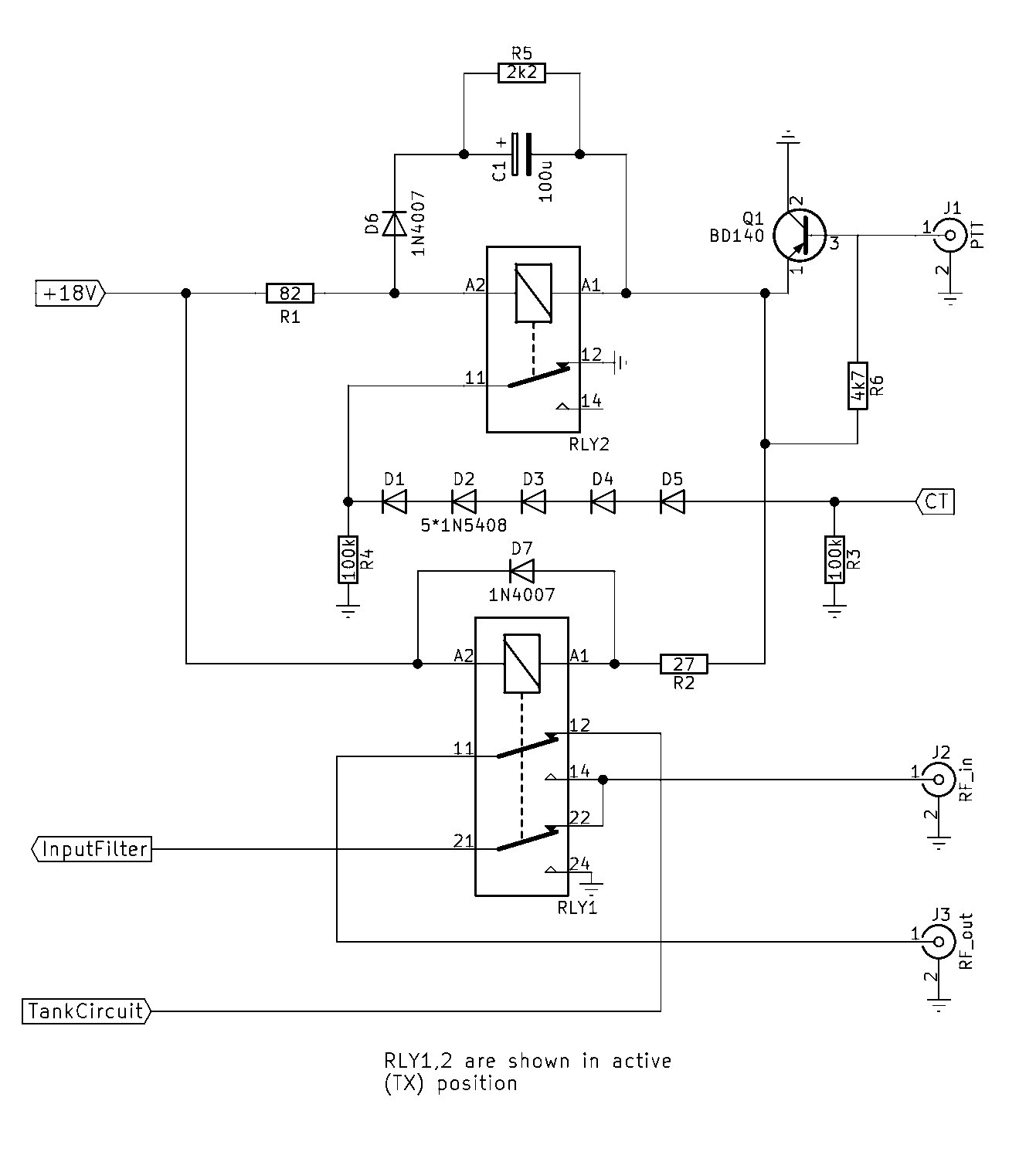
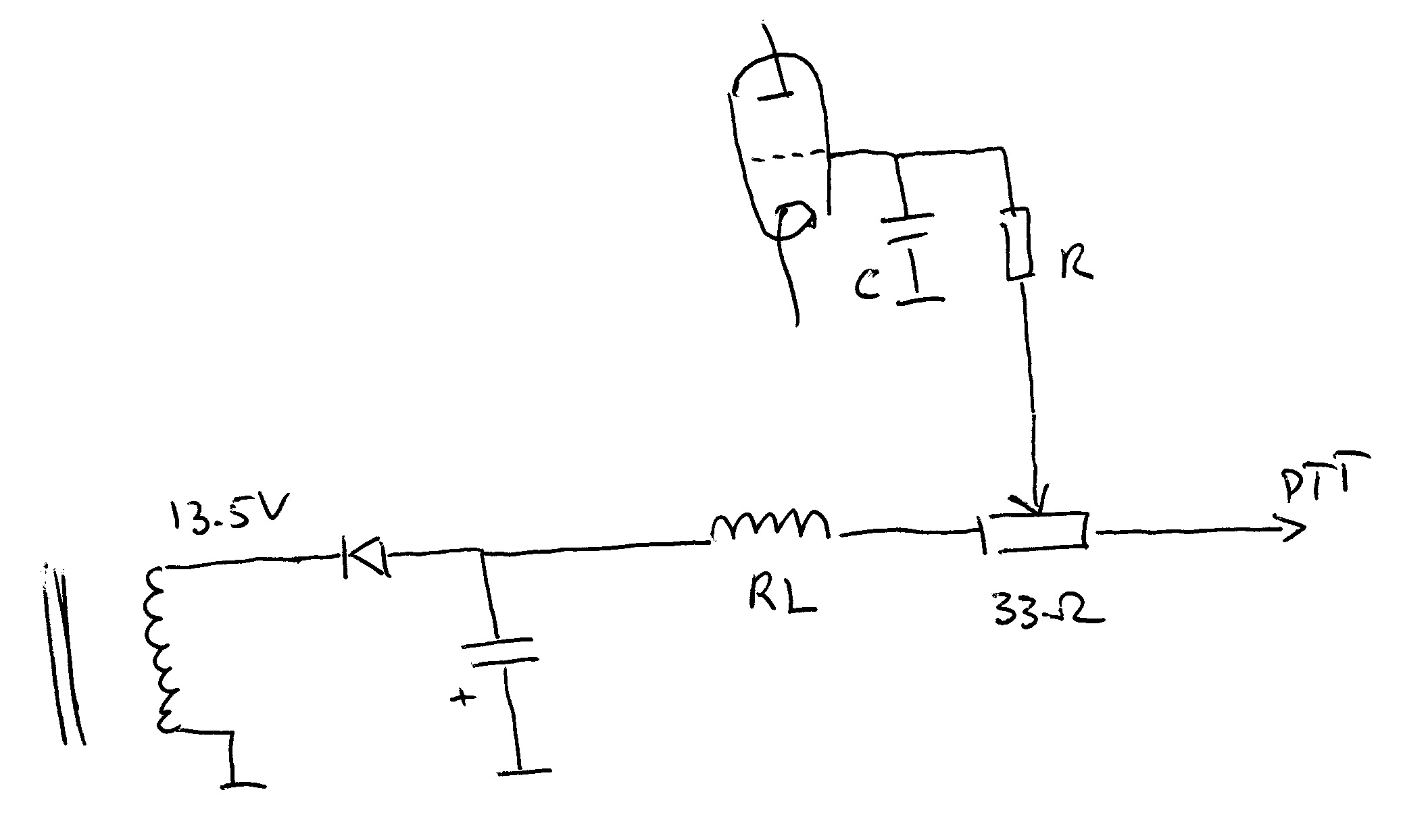
If the PTT contact is open, the grids are at about -18V, when PTT closes, all the current through the coil of the T/R switchover relay RL goes through the PTT contact, and the grids are at 2-3 Volts. The grid resistor R is 33 Ohms, and the grid capacitor C is 200pF in the original circuit.

It is better to ground the grids directly.

Although many RF tube PAs from the 1970s and 1980s have exactly this design, it was decided to ground the grids directly. That is, R and C are removed (as well as the ALC circuit that was also connected to the grids). Instead, the grids of the two tubes were directly connected to ground. Since there was already a short silver wire from the chassis to each of the unused pins at the tube sockets, this wire was simply routed to the grid pins, as shown in the following picture. Note that many components have been removed from this compartment, and how clean it looks now! The only parts left are the cathode choke (bottom right) and the input matching circuit with the inductance coils at the bottom, the doorknob capacitors and some free-standing capacitors in the middle.


During this procedure it was also found that one of the grid capacitors has split into two parts, and that the grid resistors looked "toasted" and had reduced their value to 15 Ohms. Consequently, amplification and output power came back to the expected performance after doing this modification.

> Implementing "Cathode bias" and sequence control

With grids grounded directly, we have to apply a positive bias voltage to the cathodes. To this end, the center tap (CT) of the filament transformer was disconnected from ground.
Attention: There was a small black wire going from the center tap to the ground contacts of the ALC/PTT connections. This is easily overlooked but has to be removed from the center tap, and the ground post of the PTT connection has to connected to the chassis.
To avoid "floating" cathodes, the center tap can now be connected to ground via a 100 kOhm (2W) resistor. Now the tubes "seek" their bias, and with less than 1 mA anode current, the cathodes go to cut-off (15 - 20 Volts positive). Re-connecting the center tap of the filament transformer to ground activates the tubes, this is now done with a second relay. The overall schematic is here:

New Bias Schematic

The relay at the bottom (RLY1) is there as in the original schematic, including its connection to the input filter, the tank circuit and RF in/out jackets. The only new component here is the flyback diode D7 which delays the disconnection of the antenna from the tank circuit in the TX-RX transition. The top relay RLY2 connects center tap (CT) of the filament transformer to ground via 5 diodes, the voltage drop across these diodes determines the cathode bias voltage. The "safety" resistor R3 has been mentioned above and is positioned in the chassis close to CT, and another one (R4) is mounted on a small board carrying RLY2, R1, D6, C1, R5. The resistors R2 (27 Ohm) and R1 (82 Ohm) are there to interface the 12V-relais with the (positive) 18 Volts available. Capacitor C1 delays RLY2 in the RX-TX transition, diode D6 prevents that this delay also occurs in the TX-RX transition (instead, C1 is discharged via R5 during RX). The PNP power transistor (BD 140) takes care that the PTT contact only has to sink about 2 mA, while the two relais together (emitter current of Q1) draw about 180 mA. I have mounted this transistor on a small heatsink. Note that the capacitor and the diode directly at the 13.5 Volt side of the transformer have been reversed (rotated by 180 degrees) to have a source for positive 18 Volts. During TX, the relay current of RLY1 (150 mA) goes through R2 (nominal dissipation: 600 mW) which is a 2W metal oxide type, and the relay current of the new RLY2 (30 mA) goes through R1 (nominal dissipation: 75 mW) which is also a 2W metal oxide type. With a two-channel USB oscilloscope (the second channel was used to trigger one-shot traces), the timing has been measured. The result is:

RX-TX transition: 8 msec after PTT, the T/R switchover relay starts to connect the antenna to the tank circuit. There a lot of bouncing during 2 msec, but 10 msec after PTT, the output "sees" the right load. 12 msec after PTT, the cathode voltage (measured at CT) drops from 16 to 3 Volts (tubes become active).

TX-RX transition: 7 msec after PTT goes up, the cathode bias measures at CT jumps from 3 to 16 Volts (tubes are cut off). It takes 16-18 msec after PTT before the antenna is removed from the tank circuit. This huge delay comes from the large coil of RLY1 and the flyback diode. One could possibly adjust this delay using a Zener diode, but this has not been done.

> Re-aligning the input circuit

I re-aligned the input circuit according to the instructions in the manual (removing anode voltage and adjusting for minimum SWR on the cable connecting the transceiver with the PA). Grounding the grid changes the input impedance so this step is important, furthermore, it is not a bad idea after several decades of use to do so.

> Replacing the Anode Resistors

The anode resistors (22 Ohm 2 Watt each) that are mounted within the parasitic suppressor coils also wear out sometimes. The picture shows them after I removed them, and the lower one it really looked "toasted" and the resistance was reduced to 15 Ohms. These were replaced by having two parallel 47-Ohm-2-Watt MetalOxide resistors (second picture).
  

Amplification and output power

Now I am very happy with the PA. The amplification is about 11 dB, so it makes about 65 Watts (key-down CW) if driven with 5 W, and about 130 Watts if driven with 10 Watts. For CW, I limit the drive to about 30 Watts and get 350 Watts output. Beyond 30 Watts drive, the amplification reduces because the PA hits the limits of the power supply. Driving the PA with a two-tone signal, one can go up to 60 Watt PEP drive and gets about 590 Watt PEP out. This is not bad for a 50-year old gear. Note when driving with a two-tone signal, the average power is only half of the PEP value, and in the envelope peaks the anode current comes from the el-caps in the power supply. I should say that I re-wired the transformer for a primary voltage of 234 Volts, which is above what is actually availabl. The measured anode voltage is now about 2200 V in stand-by, and drops slightly below 2000 V during CW key-down. While reducing the voltage perhaps costs some power, it is believed to increase the life-time of the device. The re-wiring has been done because the mains voltage in my country has changed from 220 to 230 Volts.

Improved cooling with an external fan.

A 120mm 12-Volt fan from a PC power supply from electronic scrap was taken and laid on the case just above the tubes. It must be positioned such that the airflow is upwards, then the fan needs no fixation (it produces under-pressure and therfore sticks to the case while running). The picture shows how it looks. I did not take care to obtain power for the fan from within the FL2100, under normal operating conditions, there is 12 V available in my shack.

External fan

The fan is not fixed. It has to be removed while not running, since then in hinders rather than supports air flow.

The question now whether this fan has some effect. To measure this, a thermo-element has been inserted in the
high-voltage compartment and fixed with a cable tie. Then, the PA has been switched on and the temperature has been measured for 90 minutes.
At the beginning of the experiment, the fan was not yet mounted. The following table shows what has been done within the 90 min of the experiment and displays the measured temparatures:

Time
[min]

Action
Temperature
[deg C]

0
Start of experiment: PA switched on, no anode current (standby mode), fan not yet mounted
23.1
5

27.1
13

31.2
19

32.7
30
PA switched to "operate" and PTT active, but no input signal. Anode current about 50 mA (100 W anode dissipation)
33.7
40

54.0
45

56.1
51

58.0
63
Fan put in the position as shown in the picture.
59.1
69

50.0
76

48.8
78
PTT removed (thus no anode current)
48.7
89
End of experiment.
34.8


Result: The fan reduces the "zero signal" temperature by about 10 C (from 59 C down to 49 C) and is thus highly recommended.

Note that in this "zero signal" mode, the tubes produce about 150 W heat (50 W from the filaments, 100 W from the anodes). In typical operation, I guess the heat will be about twice as large (50 W filament, 250 W anode dissipation), so a 100% duty-cycle zero-signal test should be a good approximation to "real" operation. Of course, if driven hard, the temperature will be higher, but then the fan should even be more beneficial!


DL1YCF, November 2018.