piHPSDR and HermesLITE-2:
RX calibration and PURESIGNAL

Recently, I obtained a HermesLITE-2 (HL2) SDR. It comes in a small metal box and contains the HL2 board as well as the N2ADR filter board which offers low-pass filters for the TX signal. The HL2 board contains a 5 Watt PA, and the N2ADR board also provides an RCA connector to key an external PA. Here I briefly report on experiments with the HL2 using the piHPSDR software.

RX calibration, ADC clipping

A signal generator was connected to the HL2 via an attenuator with about 38 dB attenuation. The signal strength as displayed by piHPSDR is given in the next table below, both with and without the N2ADR filters active during RX (the default setting is that they are active both upon RX and TX). To provide a reference value, the reading as obtained with my ANAN-7000 radio is given as well. The measurement was made at 14.2 MHz and the "RX gain" slider was set to minimum gain (-12 dB).

Signal Vpp ANAN-7000
reading
HL2 reading
with N2ADR
HL2 reading
without N2ADR
1.00 V-34 dBm-31 dBm-30 dBm
0.71 V-37 dBm-34 dBm-33 dBm
0.50 V-40 dBm-37 dBm-36 dBm
0.10 V-54 dBm-51 dBm-50 dBm
0.01 V-74 dBm-71 dBm-70 dBm


So there is a systematic error, the signal strength displayed is 3 dB too strong with the filter board active. This can be corrected by changing the "RX calibration" value in the Radio menu of piHPSDR from the default value (14) to 11. Having done this, the signal strength readings of the HL2 match those of the ANAN-7000.
The signal source was set to 1 Vpp (-34 dBm signal at the HL2 antenna) and the RX gain slider (that control the built-in preamp of the AD 9866 chip) was now slowly moved to larger amplification. The reading stays at -34 dBm for quite some time until the RX gain slider reaches +33 dB, then the signal strength reading moves down (towards more negative numbers). This is the onset of ADC clipping, because the IQ amplitude has reached the maximum value.
This statment is given more substance by the following experiment: while still feeding a -34 dBm signal at 14.1 MHz, the HL2 was set to 28.2 MHz and there one sees a weak overtone of the input signal, if one moves the RX gain slider all the way from -12 dB to +33 dB. But when moving it from +33 to +34 dB, all sorts of artifacts arise in the spectrum display.

This means that with a -34 dBm input signal and the preamp set to +33 dB, the ADC starts clipping.

Through a sequence of measurements on all bands brom 160m up to 10m, it was verified that the insertion loss of the N2ADR filters upon RX is about 1 dB in all cases.

Cross-talk in the RX/TX relay

Note: This measurement was done with a temporarily modified version of piHPSDR which does not change the preamp setting when switching from RX to TX.

There is some cross-talk in the RX/TX relay such that when TXing, part of the TX signal "arrives" at the RX. Because I want to use this accidental feed-back signal to do adaptive pre-distortion (PURESIGNAL), I first measures how much actually arrives at the RX front end. To this end, piHPSDR was set to "Duplex" mode (that is, RXing continues while transmitting) and the signal strength was measured. The RF output was set to about 5 Watts. The following table displays the measured signal strength on various bands:

Band 160m80m40m20m10m
RX level-38 dBm -33 dBm -26 dBm -20 dBm -16 dBm

This means that the RF isolation of the TRX relay is strongly dependent on the frequency and varies from about 75 dB (160m) down to 53 db (10m band), and that using this signal for PURESIGNAL feedback one has to cope with a wide range of feedback levels.

PURESIGNAL "barefoot"

From other measurements performed in the course of this work, it follows that the ADC needs to "see" a feedback level that corresponds to a RX signal strength of about -6 dBm when the RX gain slider is at zero (0 dB) position. Since the "cross-talk" feedback level is much weaker, a preamp setting of +32 dB (160m band) to +10 dB (10m band) is necessary. The PURESIGNAL calibration loop determines the value of a hypothetical "TX attenuator" between 0 and 31 dB, so we must take care that "TX attenuator" settings between 0 and 31 map to preamp settings that encompass the above window.

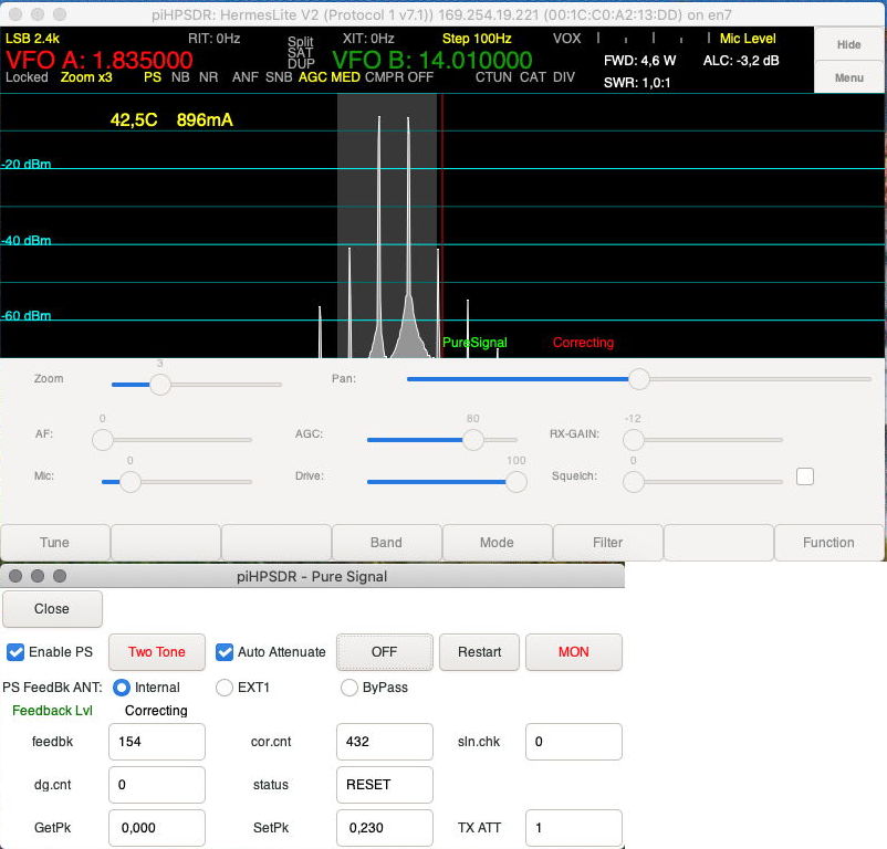
To this end, in my version of the piHPSDR program (on github.com/dl1ycf) the preamp range is +2 to +33 dB if "Internal" feedback is chosen in the PS menu (see pictures) while the range -12 to +19 dB is chosen if either "EXT1" or "ByPass" feedback is chosen. Note that there are no relays within the HL2 that control the feedback path, so the only effect of the choice "Internal" vs. "EXT1" is the mapping of the TX-att values to preamp settings.

With "Internal" feedback selected, PURESIGNAL worked well with "cross-talk" feedback from 160m to 10m.


In the following, I show some screen-shots from the piHPSDR program to demonstrate the effectiveness of PURESIGNAL on 160m and 10m, followed by a measurement with an external spectrum analyzer on the 20m band to show that the display of piHPSDR actually shows the reality. The following six pictures all are at least 800 pixels wide but displayed smaller to get them side-by-side. You can easily display them enlarged.

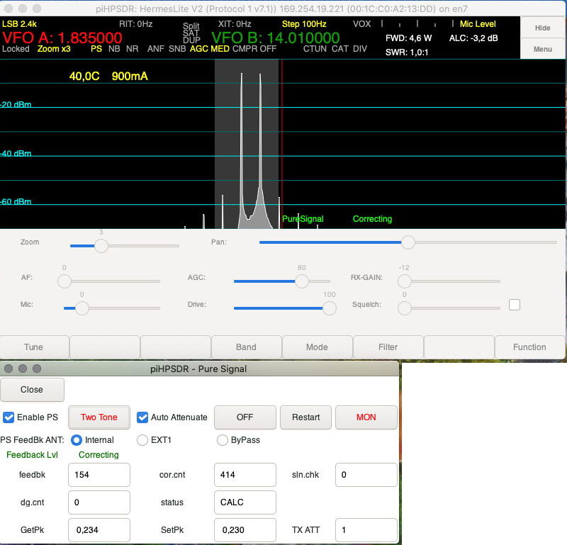
We start with 160m (left: PURESIGNAL off, right: PURESIGNAL on). One sees that the feedback level calibration loop has found optimum feedback with TXatt=1, meaning that the preamp is set to +32 dB. To the left, one sees the uncorrected signal from the HL2 PA which shows IM3 about 35 dBc, and this improves to about 50 dBc with PURESIGNAL active.


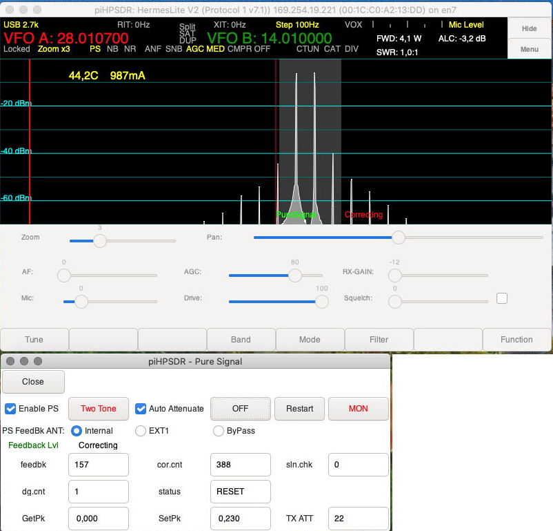
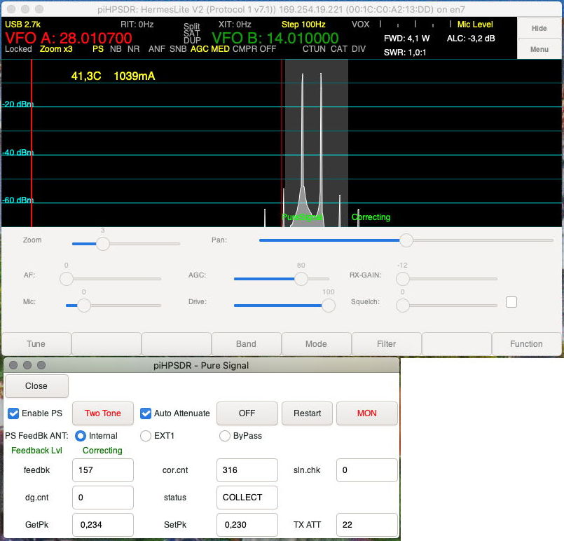
Now, we show the same on the 10m band and get essentially the same result, except that the optimum TXatt value now is 22, which maps to a preamp setting of +11 dB. These settings are determined by the PURESIGNAL calibration loop of the piHPSDR software and match the expectations based on the measured TRX relay cross-talk.


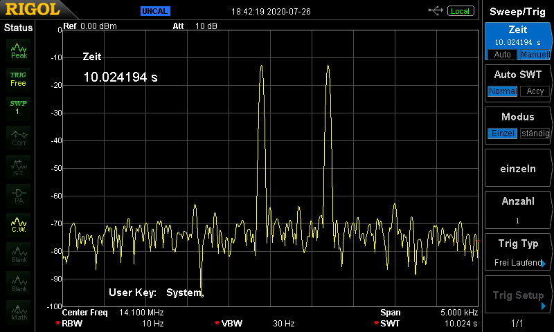
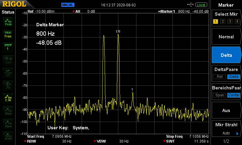
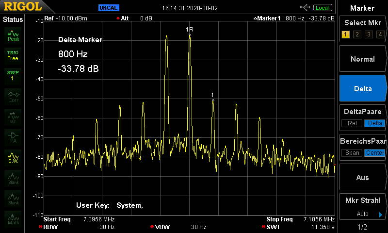
Now the proof of the pudding definitely is in the eating, so we show the HL2 output signals measured with a spectrum analyzer on the 20m band. The figures (IM3 of 50dBc/35dBc with/without PURESIGNAL active) are the same as those derived from piHPSDR's panadapter (left panel: without PURESIGNAL, right panel: with PURESIGNAL)


PURESIGNAL with external feedback

Using external feedback is necessary if an external PA is to be included in the PURESIGNAL correction loop. To this end, we need an SMA jack at the HL2 case which connects to the "RF3" input of the HL2 board. Fortunately, the HL2 and N2ADR boards are connected with a small daughter-board such that soldering a small coax cable there (coax center: pin 6, coax shield: pins 3+4) is easy, as documented by these pictures (thanks to DL2RMM for the hint):


Note: For a correct "symmetric" attenuator, this will lead to a -3 dB damping during RX, because then the attenuator puts an additional 50-Ohm load on the RF input. Steve KF7O therefore suggests a "two-stage" attenuator with an unsymmetric second stage, as sketched here:


With 1:30 turns, the first stage has about 30 dB damping. To reduce the adverse effect of having this connected to the RF input during RX, Steve's idea was to have R2 larger than 50 Ohm (say, 300 Ohm). For 300 Ohm, the input impedance or the RX drops to 43 Ohm and the damping of the RX signal is of the order 1 dB. Choosing then R1 as 1200 Ohm, the second stage has a nominal damping of about 29 dB (for a 50-Ohm load), so the overall damping is would be sufficient to safely connect a HL2 for a 1000-Watt PA. If your PA has only 100 Watts, you can choose a smaller value for R1 (or increase the number of turns on the toroid in the first stage). It is not recommended to omit R2 since this ensures that there is a voltage divider in the output if connected a high-impedance load (note that the second stage only has 14 dB attenuation in this case). In this two-stage scenario, it is also possible to reduce the left-most (50 Ohm) resistor to increase the damping.


As a result, the HL2 case has an addition "RF3" input jack where one can inject the feedback signal coming from an external attenuator:


Then I connected the HL2 to the old FL2100 two-tube RF amplifier (see the report on reviving/modifying of this PA here on my web pages). The PA makes about 50-70 watt when driven with 4-5 watt from the HL2, and the signal is rather clean when using PURESIGNAL with external feedback (the 60 dB attenuator also described on this web site was used):


One might speculate that the "cross-talk" feedback, with is still present and superimposes with the external feedback, limits the PURESIGNAL quality a little bit, and "only" -48 dBc IM3 have been obtained. This is however a big step forward, since without external feedback the best one can do is to use "cross-talk" feedback to produce a clean HL2 signal that goes to the PA. This way, one sees the intrinic non-linearity of the external PA, so in my case there were IM3 satellites at -34 dBc and IM5 satellites slightly below.


So the bottom line is: Producing a clean signal with HL2 + external PA requires using external feedback to include the external PA in the PURESIGNAL correction loop.


DL1YCF, August 2020