Adding a -60dB output
to a MJF 267 DummyLoad/Wattmeter
Note on the MFJ267: It is a good idea to calibrate the meter after purchase. However, in the MFJ267 manual I found no instructions
how to do this.
Luckily, the meter circuit board is the same as in the MFJ 815d Watt-meter, so the instructions for calibration found in the
MFJ815d manual can be used to calibrate the meter of the MFJ 267 as well.
The -60dB output is very useful for monitoring your transmitted signal. You can feed your attenuated TX signal to a second radio,
to a spectrum analyzer, or to an oscilloscope. At the auxialiary output, you get a -20dbm signal if your TX makes 10 Watt,
and this increases to 0dBm if your use 1000 Watt. This is OK for using a spectrum analyzer, an oscilloscope or for using
this to make pre-distortion with an SDR transceiver (see my PURESIGNAL page). For checking your
signal with a second radio, you may need an additional attenuator since -20dBm are already S9+53dB.
Of course, when doing measurements the MFJ 267 should be in "DummyLoad" mode, but to constantly monitor the signal while TXing
(e.g. when doing pre-distortion), the MFJ 267 can also be in "Antenna" mode.
The circuit is actually quite simple:
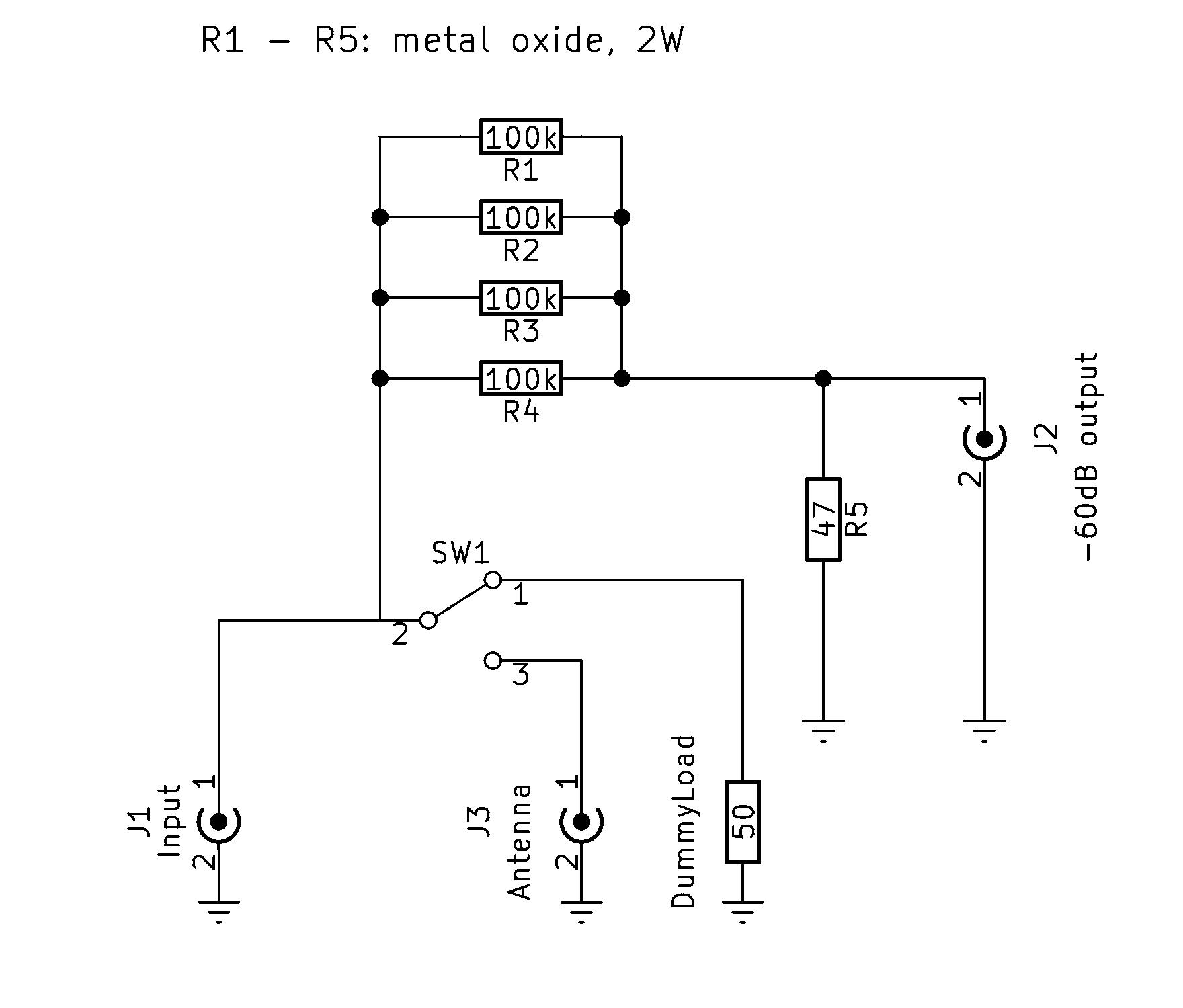
The bottom part is the original dummy load, R1 through R4 make a 25
kOhm series resistor. The shunt R5 is necessary for two reasons: first,
it suppresses high voltages at the output if connected to a
high-impedance oscilloscope input, and it takes care the output side
also "sees" a correct (about 50 Ohm) termination. Note that the damping
is -60dB only if J2 is connected to a 50 Ohm load, if connected to a
high-impedance load, the attenuation will only be -54 dB. With 1000
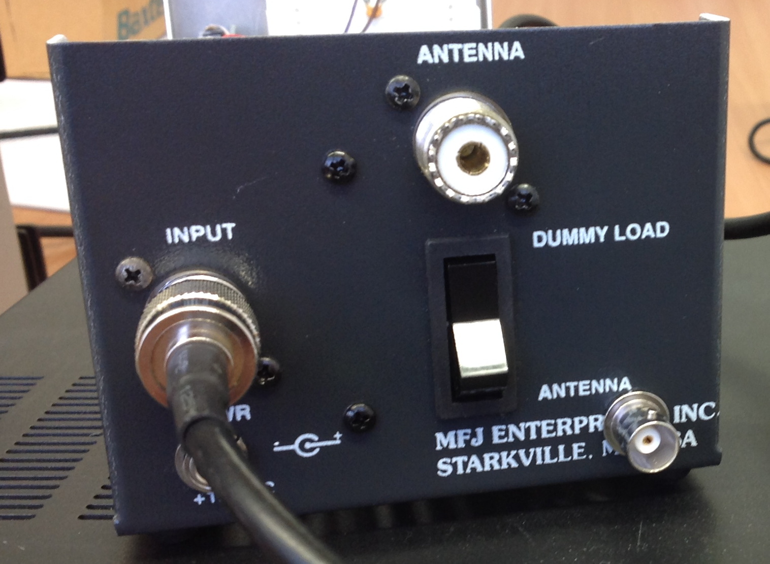
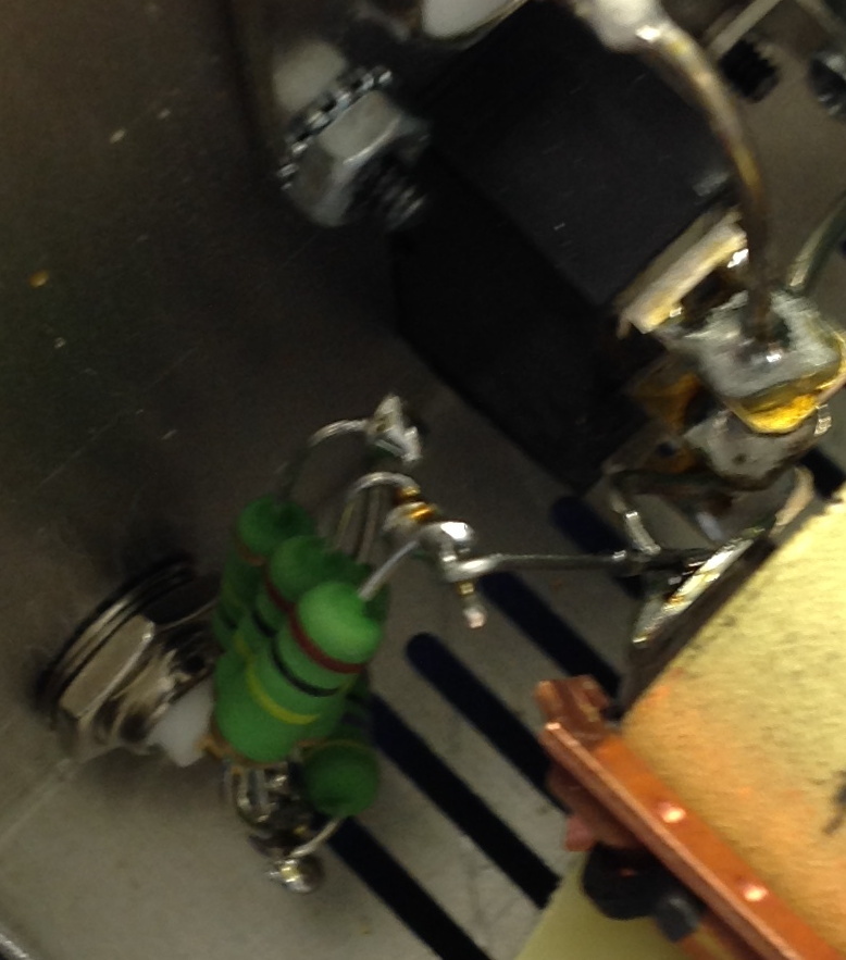
Watts input, R1-R4 together dissipate 2 Watts. The following two
pictures show how a BNC jacket (J2) is mounted at the back of the
MFJ267 and how the resistors are connected:
Results
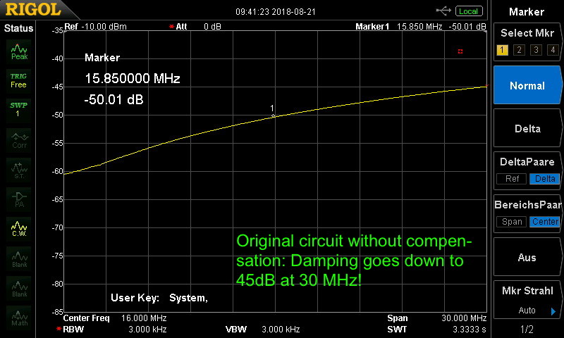
Already the first measurements with an oscilloscope showed that the
attenuation is about as intended for low frequencies, but gets much
less for higher frequencies. A first measurement with a spectrum analyzer / tracking generator indeed shows that the damping goes down to 45 dB at 30 MHz:
This is the result of stray capacitances between the input and the
output, and the curve also looks different if the switch is in "Dummy
Load" or "Antenna" position. A simulation shows that the stray
capacitance is about 1 pF and should be compensated by a capacitor of
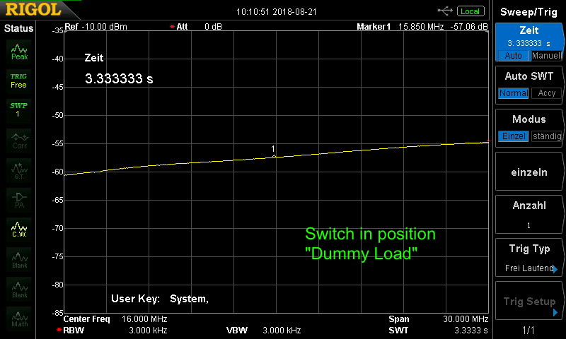
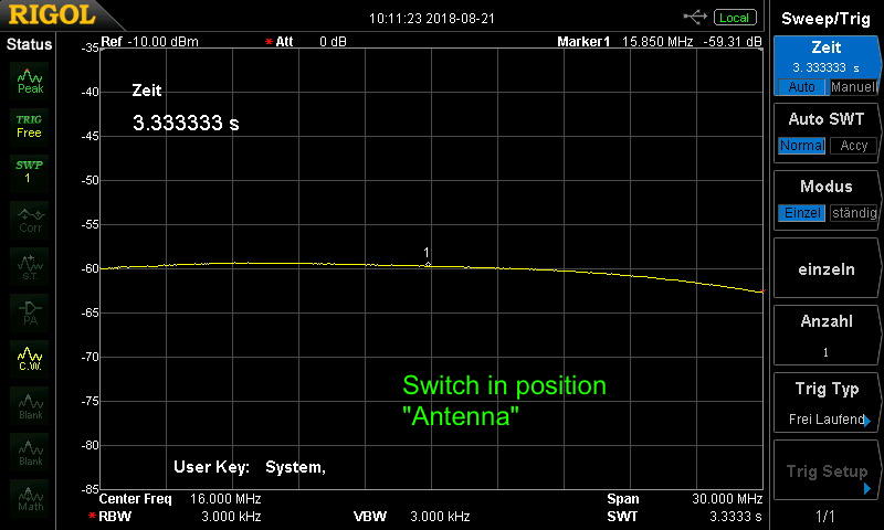
about 1000 pF parallel to the 47-Ohm resistor R5. The following two
pictures show the final result for both cases, where the TX signal
heats the DummyLoad or goes to the antenna. We still have a variance in
attenuation of slightly less than 5 dB when going from 1 to 30 MHz, but
this we cannot fix since the stray capacitance is so different for the
"Dummy" and "Antenna" switch positions. In the first case, the damping
goes down to 55dB at 30 MHz (one would need a slighly higher compensating
capacitor), in the second case, it goes up to 63 dB (one would need a slightly
smaller capacitor). Still, introducing the capacitor parallel to R5 is a
huge improvement.
DL1YCF, September 2018.